Loading...
U3 Building, No.6 Lianpu Street, Huangpu District, Guangzhou, China
info@renepoly.com
+86 (20) 3180 0796

Intelligent Energy Management System

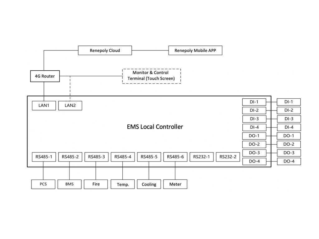
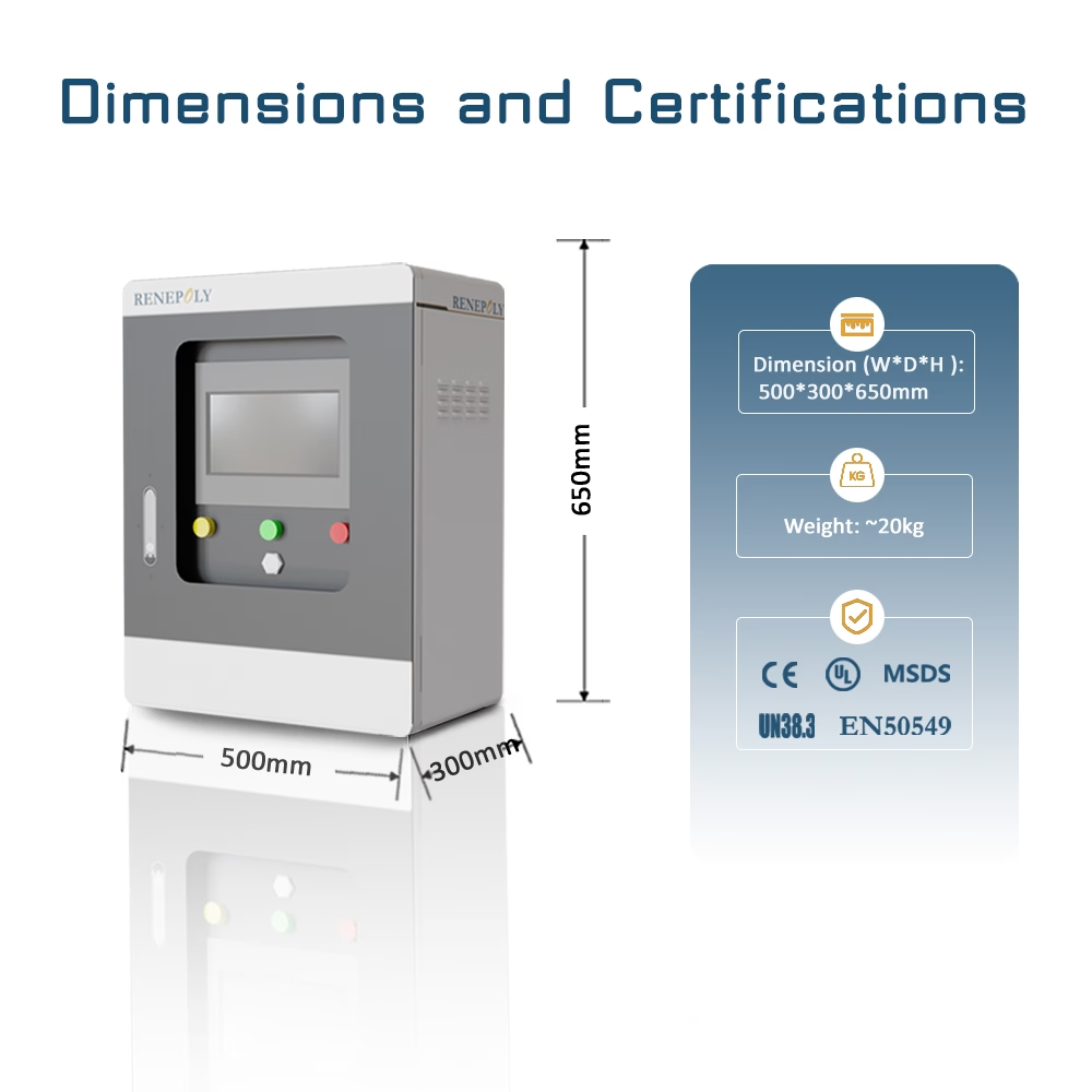
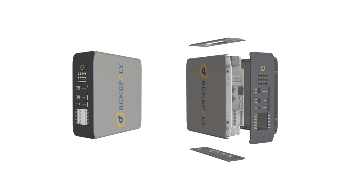
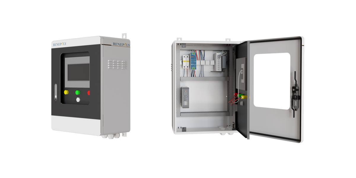
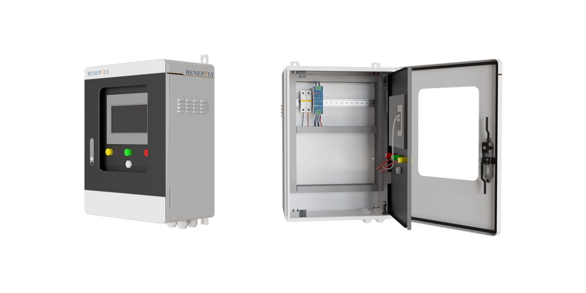
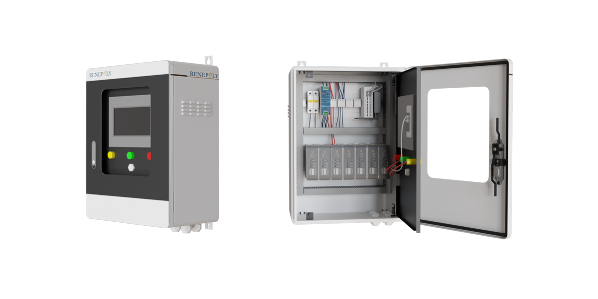
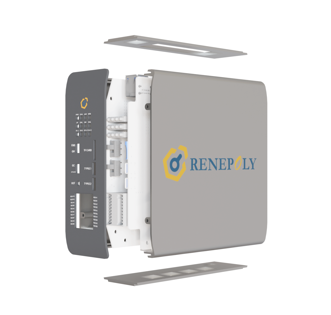
Renepoly Cloud is an energy management system and cloud platform developed specifically for microgrids. Its hardware includes EMS local controller, EMS local display and control terminal, and 4G router device; its software includes microgrid management program deployed locally on EMS local controller, EMS cloud platform deployed on remote server, and mobile APP. The full set of Renepoly EMS products ensures the normal operation of microgrid system and meets the real-time monitoring of microgrid by operation and maintenance personnel anytime and anywhere.

Try the online Demo!

EMS Functions

Data collection and monitoring

The EMS energy management system can monitor the data information of site equipment (including PCS, BMS, battery cells, electric meters, loads, gas turbines, etc.) in real time, display it in the monitoring screen, and store it in the database. Analog quantity measurement: collect and process the voltage, current, active power, reactive power, frequency, power factor, etc. of the main equipment of all controlled stations. State quantity measurement: equipment operation alarm signal, etc.

Data processing and analysis function

The EMS system can realize simple processing of data information. Telesignal processing includes: telesignal signal inversion and telesignal signal displacement. It can automatically identify the accident displacement according to the total accident signal and protection signal.

Analysis and statistics functions include daily charge and discharge calculation of energy storage system, total charge and discharge calculation, total power addition, power factor, load rate calculation, etc. Analyze and statistically analyze the voltage, temperature, SOC and other information of single battery and battery cluster, and display them in the form of curves, bar charts, etc.

Operation control function

The EMS system realizes real-time control of energy storage charging and discharging power, demand, liquid cooling air conditioner on/off, etc. according to the needs of strategic operation. Ensure the stable, efficient and safe operation of the entire site.

Event alarm function

The EMS system provides an open intelligent event alarm function. According to the level of event alarm, alarms are generated and saved according to type and level. Event alarms are divided into program operation alarms, telemetry alarms, telesignaling alarms, communication fault alarms, and user operation alarms according to type; they can be divided into ordinary alarms, important alarms, and emergency alarms according to level.

Graphic display

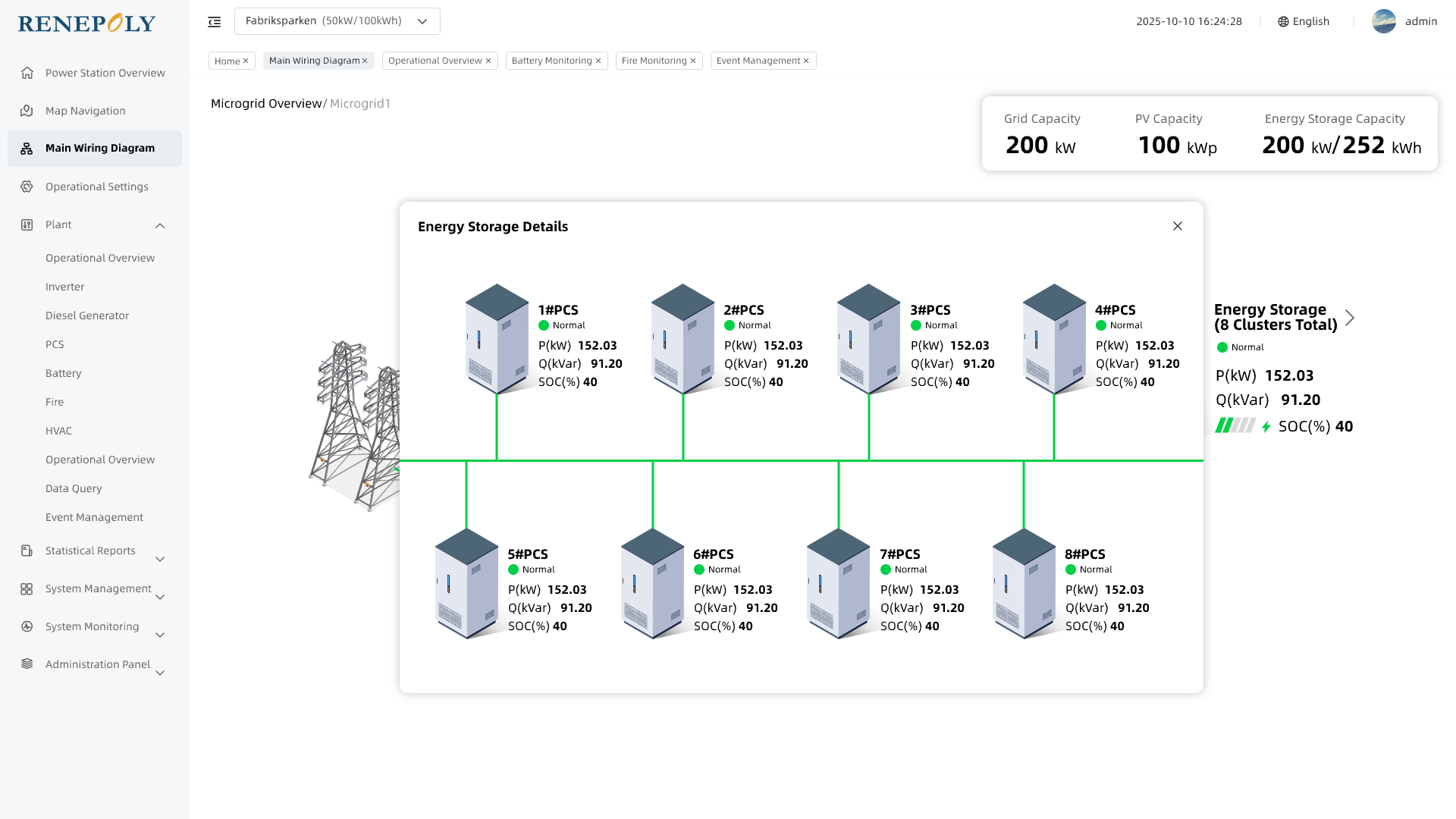
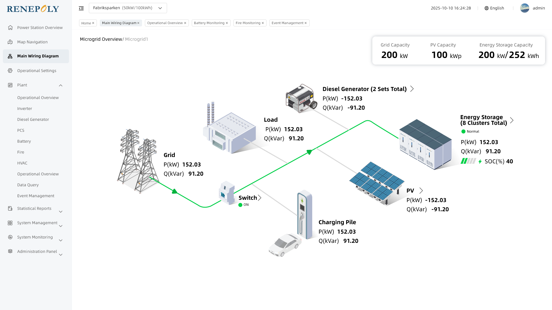
The graphic system is based on relational databases and multimedia technology to realize rich graphic data display, and supports convenient operations such as full graphic human-computer conversation interface, navigation diagram, structure diagram, curve diagram, bar diagram, mixed diagram, working condition diagram, table, etc. It can display screens such as main wiring diagram, equipment monitoring diagram, operation report, energy control, communication status, etc., and can quickly call up the screen through keyboard, mouse, etc.

The graphics system supports the simultaneous display of real-time data, historical data, etc. on one screen, and the screen data can be flexibly configured and freely combined by users. At the same time, the rich dynamic graphic element controls of the graphics system can dynamically display the energy storage percentage capacity, display the power flow direction, and display the two-level telemetry limit in different colors. Telemetering information such as equipment status and operation mode can be directly displayed in dynamic text information, making the screen simpler and clearer.

All historical data in the background can be displayed and historically reviewed with hours as the horizontal axis and minutes as the interval, and the historical storage time is greater than 1 year. The data can also be displayed in the form of a report to show the data required by the customer. It can display power data in units of days, such as daily charge and discharge.

User authority setting function

Users can set PCS and BMS working parameters according to current needs and set working parameters according to system operating conditions and environmental conditions. Different users log in and set parameters according to different permissions.

Data forwarding function

It can realize communication with the owner's backend system, and use the agreed protocol to send the data information of the energy management system platform to the owner's backend.

SOC maintenance control

Real-time monitoring of energy storage SOC and charging and discharging power to keep the energy storage battery SOC within a reasonable range.

Smooth and stable control

The system realizes real-time control of distributed power generation power, energy storage charging and discharging power, load, etc. according to the needs of strategy operation. Ensure the stable, efficient and safe operation of the entire site.

Power generation side - real-time monitoring of power generation, by controlling the charging and discharging of energy storage batteries, or controlling the power generation output of other energy generation forms to reduce the sudden change of distributed power output, so that the distributed power output is smooth;

Grid side - real-time monitoring of grid output power, by controlling the charging and discharging of energy storage batteries, control the grid output power;

User side - real-time monitoring of user power consumption, by controlling the charging and discharging of energy storage batteries, realize the peak shaving and valley filling of user power consumption curve, and realize economic operation.

Planned operation mode

With a resolution of five minutes, set the all-day charging and discharging strategy to enable users to achieve peak and valley price difference benefits, and support multiple plan curve switching.

On-grid and off-grid switching control

The system detects the switch status of the grid connection point and the on-grid and off-grid status sent by the equipment, determines the current on-grid and off-grid status of the system, and automatically switches the on-grid and off-grid control strategy.

Demand management control function

Real-time monitoring of the power value of the system grid connection point, by adjusting the charging and discharging power of the energy storage system, effectively controlling the grid connection point power within the set range. According to the policies of different regions, through demand electricity fee management and demand-side management, help users reduce demand electricity fees and electricity fees, and obtain additional profit points.

System protection function

EMS is a key subsystem for the execution of protection strategies of the energy storage system, monitoring BMS, PCS, fire protection and energy meters and other equipment. EMS receives fault information from BMS and PCS. EMS monitors fire protection and energy meters, etc. EMS monitors these equipment fault information and equipment signal fault information, controls the system to standby or shut down, and ensures the safe and reliable normal operation of the system.

Auxiliary black start function

By starting the generator sets with self-starting capability in the system, the generator sets without self-starting capability can be driven, gradually expanding the system recovery range and eventually achieving the recovery of the entire system.